Data-Decoding Method Using AI in Multi-level Amplitude Modulation Holographic Memory
Yutaro Katano, Teruyoshi Nobukawa,Tetsuhiko Muroi,Nobuhiro Kinoshitaand Norihiko Ishii
As a next-generation optical archive storage device for 8K video, we have been researching and developing holographic memory. Recent studies have focused on multi-level code instead of binary code to increase the recording capacity and the data-transfer rate. Multi-level amplitude recording requires a novel reproduction method which can demodulate the signal accurately, even when the optical noise is superimposed on the signal. In this report, we introduce our demodulation method using AI (Artificial Intelligence) for realization of a multi-level amplitude recording system.
1. Introduction
Holographic memory is a promising technology for next-generation archival optical storage devices in which a bit sequence representing potential storage data is modulated to yield a two-dimensional (2D) image known as a data page. For a two-level (binary) amplitude-modulation scheme in which bits are encoded as bright or dark pixels, a single high definition data page can store approximately 1 Mbit of data, all of which may be written or retrieved in a single laser-illumination step. This allows holographic memories to achieve high data-transfer rates1) 2). Meanwhile, a variety of superposition methods may be used in combination with each other to achieve high storage density3) 4), while the use of photopolymers*1 in storage media enables stable retention of data over long periods5). All of these advantages make holographic memory a promising technology for optical storage devices capable of high-speed, high-capacity, long-term retention of 8K ultra-high-definition television (or simply 8K) videos and other storage-intensive data, and the NHK Science & Technology Research Laboratories (STRL) has launched an R&D initiative to explore these possibilities.
Thus far, STRL has successfully demonstrated a holographic-memory-based real-time playback system for highly compressed 8K video6) 7). This demonstration, which showcased the system's capacity for stable playback 8K video saved on storage media (at 85 Mbps), established the system as a promising candidate for practical applications. Although this system currently boasts a storage density of 2.4 Tbit/inch2 and a maximum transfer speed of 520 Mbps7), further improvements in both of these areas will be needed so that the system becomes capable of handling high-quality images with low compression and minimal quality degradation, which are essential for archival systems.
Any increase in the quantity of information that may be encoded in data pages simultaneously increases storage capacities and transfer speeds. To this end, improvements in system components—such as the spatial light modulator*2 (SLM) that displays data pages for writing or the image sensor*3 that captures data pages for data retrieval—have spurred progress toward data pages with ultra-high-definition quality and larger physical areas. However, SLMs and image sensors with higher pixel counts and narrower pixel pitches create new problems of their own, such as increasing physical footprints for optical systems, higher costs, and more complex control requirements for the higher data-transfer rates that are necessitated by greater numbers of pixels.
These considerations have spurred interest in using multi-level modulation schemes to increase storage capacities and enhance operating speeds8). In particular, multi-level amplitude modulation schemes, which read and write data pages with three or more amplitude gradations, have the advantage of allowing existing optical systems to be used with the same SLMs and image sensors used for two-level amplitude modulation, thereby obviating the need for new optical assemblies. On the other hand, multi-level amplitude signals use intermediate amplitude gradations and are thus susceptible to the influence of noise during reading and writing, which is a problem that necessitates more precise signal-retrieving techniques.
In this article, we describe a method for addressing these difficulties using an artificial intelligence (AI) mechanism that pre-learns the noise properties of an optical system and exploits this knowledge when demodulating data pages. After first reviewing the principles of holographic memory, we present a detailed discussion of the demodulation behavior of our proposed method within the context of two-level amplitude modulation and then report the results of numerical simulations using our method as applied to a four-level modulation scheme.
2. Principles of holographic memory: Data storage/retrieval and effects of optical noise
2.1 Data storage and retrieval
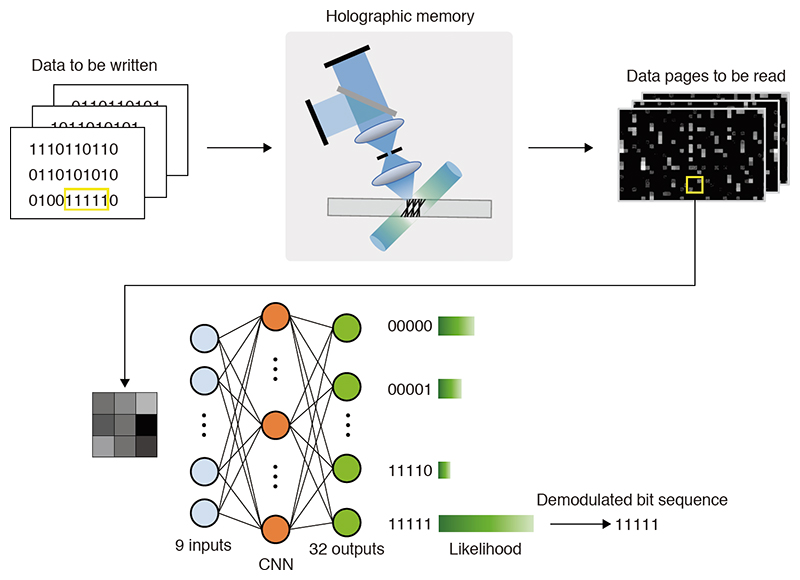
Figure 1 shows the principles of data storage and retrieval in holographic memory. For storage, a bit sequence to be written is converted into a data page, consisting of a 2D array of light or dark pixels, which is displayed by an SLM that spatially modulates the intensity of a laser beam, thus yielding the signal beam.
When the signal beam illuminates the storage medium, it is optically Fourier-transformed*4 by the lens. For this reason, an aperture is commonly placed near the Fourier-transform plane (the focal plane of the lens on which the signal beam is focused) to remove unnecessary high-frequency components and reduce the beam area, thus increasing storage density. The signal beam and an unmodulated reference beam impinge simultaneously on the storage medium, producing optical interference fringes*5 whose light-dark pattern is recorded in the form of a refractive-index distribution stored in the medium. This is the hologram.
To retrieve stored data, a reference beam for reading purposes (and only this single beam) illuminates the storage medium. There, it is refracted*6 by the hologram to yield a reconstructed beam encoding the stored data content. After the reconstructed beam is captured by an image sensor, the data page is extracted from the resulting image and demodulated to recover the original bit sequence.

2.2 Optical noise contamination and consequences for data retrieval
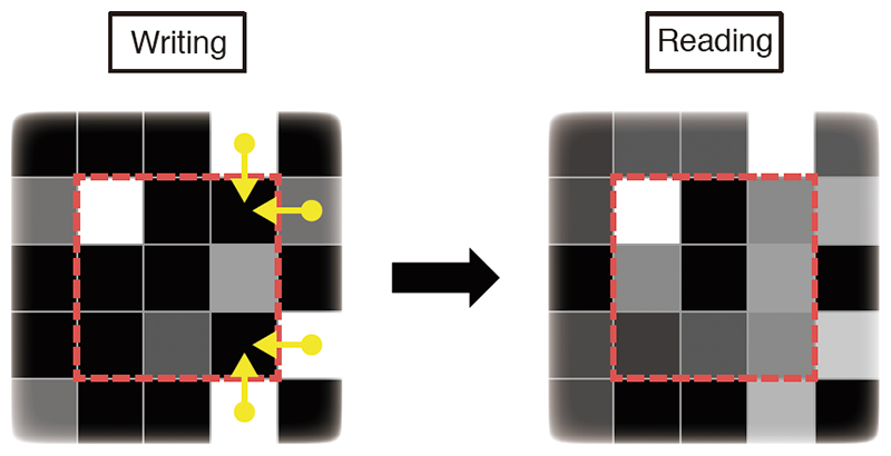
The content of stored data pages (as captured by the image sensor during the retrieval process) is contaminated by the presence of optical noise introduced by the propagation of the recording and reconstructed beams through their respective optical paths. For example, dust adhering to optical components or laser sources with nonuniform distributions of in-plane brightness can result in data loss, as shown in Fig. 2 (a), or brightness clustering, as shown in Fig. 2 (b), during the readout of data pages. Consequently, bright pixels that happen to lie in the shadow of dust particles may be misread as dark. Conversely, brightness clusters may cause dark pixels to be misread as bright.
Mechanisms like these produces what is known as fixed-pattern noise, which is characterized by the presence of noise at identical positions in all data pages read by a given optical system. The consistent nature of this noise allows the design of correction schemes in which all data in a page are added together and averaged to identify fixed noise components, which may then be subtracted to mitigate the effect of noise contamination, as has been previously reported9).
Additional difficulties are caused by image blurring, as shown in Fig. 2 (c), which may result from a lens aberration*7 or the depletion of high-frequency components when the aperture is placed at the focal point of the signal beam. Similarly, differences in pixel pitch or shifts in relative positioning between the SLM and the image sensor may cause resampling noise, as shown in Fig. 2 (d). In such cases, even assuming identical pixel pitches for the SLM and the image sensor, it is difficult to eradicate pixel shifts from data pages entirely due to lens-aberration effects.
Such blurring or resampling noise causes light from bright points to leak out into neighboring pixel regions, thereby reducing the brightness of bright points and increasing the brightness of dark points to yield demodulation errors. This is known as interpixel interference. Furthermore, in contrast to the fixed-pattern noise described above, the impact of this phenomenon is difficult to mitigate due to the different positions of bright points in different data pages, which ensure that the locations of demodulation errors differ from page to page. Consequently, interpixel interference is a major cause of reduced demodulation accuracy.

3. Using convolutional neural networks to demodulate two-level amplitude-modulated data
3.1 Convolutional neural networks for data demodulation
To improve the accuracy of data-page demodulation, we use a convolutional neural network (CNN) 10), *8, which is an AI technology particularly well suited to the task of image recognition that has advanced rapidly in recent years. For example, in the facial recognition field, images of faces captured from a range of angles under varying lighting conditions are currently being used as inputs to train CNNs to recognize facial features, and thus achieve more accurate classification of facial images. Similarly, the data pages retrieved from holographic memories may be thought of as merely another type of image data that can be used as inputs to train a CNN to recognize specific features, after which the CNN may succeed in accurately demodulating data pages, even if noise is present. In this section, focusing on the specific example of two-level amplitude-modulated data, we explain this machine-learning approach to demodulation and discuss its data-retrieval accuracy.
3.2 Modulation encoding via two-level amplitude modulation
Next, we explain the modulation process that encodes the signal of interest. Figure 3 illustrates 5:9 modulation encoding, which is used for two-level amplitude modulation encoding. In 5:9 modulation encoding, the bit sequence to be stored is subdivided into 5-bit segments, each of which is represented by a 3×3 pixels grid called a modulation block. Each data page consists of a sequential array of modulation blocks, and each modulation block contains two bright and seven dark pixels. Thus, as shown in Fig. 4, as long as it is possible to sample the brightness of the nine pixels and correctly identify the positions of the two brightest pixels, the block can be demodulated to recover the original 5-bit sequence. A demodulation scheme of this type is known as a hard decision*9. Hard-decision demodulation of 5:9 modulation is straightforward to implement and can operate rapidly, but its relative simplicity makes it vulnerable to noise-induced demodulation errors.


3.3 Demodulation via CNN
Figure 5 shows the use of a CNN to demodulate modulation blocks. A training dataset*10 consisting of a large number of data pages, together with the bit sequences used to generate them, is prepared in advance. Elements of this dataset are then repeatedly fed into the CNN to allow it to learn the features of the data pages. Modulation blocks in the training dataset are contaminated with optical noise arising from the read and write stages of the holographic memory. Thus, as the learning process proceeds, the CNN gradually acquires the ability to account for the properties of this noise when demodulating 5:9-encoded blocks. Because each modulation block encodes 5-bit data, there are 32 possible modulation-block configurations. The CNN outputs a likelihood value for each of these, and the bit sequence corresponding to the highest-likelihood block is taken as the demodulated value for the block.
As noted above, fixed-pattern noise has the property of appearing at the same positions in all data pages. This suggests preparing individual CNNs for each modulation block allows each CNN to learn the noise properties relevant for the position to which it corresponds, as shown in Fig. 6. In other words, by separately training each CNN to achieve accurate demodulation of its own modulation blocks, we can increase the accuracy of the overall demodulation process.

3.4 Structure of CNN for demodulating two-level amplitude-modulated data
Figure 7 depicts the structure of a CNN used to demodulate 5:9-encoded data. In general, CNNs consist of multiple layers, and there is a tradeoff between the number of layers and the time required to process data. Since a CNN that requires excessive computation time will reduce the transfer speed achievable by a holographic memory, we restrict our attention to networks containing just two convolution layers and two fully connected layers.
The input to the CNN is a set of nine brightness values indicating the brightness levels of the nine pixels constituting the modulation block to be decoded. The initial two convolution layers apply multiple filters (shown as brown squares in Fig. 7) that slide over the input pixel grid, applying multiply-and-add (convolution) operations involving filter coefficients and input brightness values. The first convolution layer employs 32 filters, each 3×3 pixels in size. The second convolution layer employs 64 filters, each 2×2 pixels in size. The use of multiple filters allows accurate identification of features in input data. Filter coefficients are optimized in the CNN training process.
The fully connected layers, which are used to connect the layers preceding and following them, consist of collections of units (called nodes) that are used for storing the results of arithmetic operations. The outputs of convolution layer 2 are collected by 1,024 nodes in fully connected layer 1, and these are ultimately reduced to 32 nodes (each representing a likelihood value for a single 5-bit sequence) in fully connected layer 2. Each pair of nodes is combined with a coefficient known as a weight.
Filter coefficients and inter-node coefficients are initialized to random values at the beginning of the training process, and then adjusted via backpropagation algorithm11), *11 to maximize demodulation accuracy for the training dataset until final values are determined.

3.5 Results: Demodulation of two-level amplitude-modulated data
We used data obtained from an actual optical system to test the accuracy of our demodulation technique. For these tests, we used data pages consisting of 1,740×1,044 pixels, as shown in Fig. 6. Since this results in 201,840 modulation blocks per data page, we prepared this number of CNNs. Next, from a total of 864 data pages recorded by angle-multiplexing*12, we selected 700 pages for use as training data and 164 pages for use as test data.
An overview of the learning process is shown in Fig. 8, where we see that the CNN demodulation accuracy (shown as the fraction of correct CNN outputs) gradually increases with the number of training epochs*13. However, the nature of the noise contamination affecting distinct regions of the data page ensures that different CNNs learn at different rates. This means that the learning process requires particularly long times in high-noise regions.
In Fig. 8, we show the results for just a small sample of the full set of modulation blocks. However, these results are representative of what is typically observed overall, with the CNNs for many regions effectively completing their training within 30 epochs. Nonetheless, these tests did reveal the existence of CNNs whose training required as many as 200 epochs. Since imposing a uniform cutoff on the number of training epochs for all CNNs may result in underfitting or overfitting*14, we used an early-stopping method12) to interrupt the learning process before overfitting occurs. Similarly, we apply dropout*15 methods during training to avoid overlearning.
Next, we compare the demodulation performance of our CNN approach to results obtained via conventional hard-decision methods. Figure 9 shows the total number of bit errors encountered in the demodulation of 164 pages of test data. Here, it should be noted that our CNN method produces fewer errors than the hard-decision method for all pages in the dataset. Overall, the CNN method achieves a mean bit-error rate of 3.4×10⁻⁴, which amounts to a reduction of roughly fourfold compared to the corresponding value of 1.2×10⁻³ incurred by the hard-decision method.
These results indicate that a more detailed analysis of the efficacy of CNN demodulation is needed. First, from Fig. 9, we can see that the superior accuracy of CNN versus the hard-decision method is particularly prominent in the vicinity of modulation blocks #1 and #201,840. These regions correspond to modulation blocks lying near the outer perimeter of the data page and are thus particularly susceptible to the effect of lens aberration caused by the optical beam used to write and read data from the storage medium. The reduced bit-error rates achieved by the CNN method in these regions demonstrate the ability of the method to decode modulation blocks correctly, even in the presence of aberration effects.
Next, we investigated the modulation blocks with indices 48,078 and 48,658. These two blocks, which lie adjacent to one another in the vertical direction within the data page, are responsible for more bit errors than any other page location. Figure 10 shows two examples of cases in which bit errors arise in hard-decision demodulation solely among the 164 pages of test data. Considering the upper-right pixel of block 48,078 and the center-right pixel of block 48,658, we can see a noticeable decrease in brightness occurring either during writing or reading.
As similar behavior was observed for multiple data pages (pages 50 and 108 in the case of Fig. 10), we attribute this to the effect of fixed-pattern noise, which caused the hard-decision method to produce incorrect detection of second-brightest pixels, thus causing bit errors. In contrast, the CNN was able to demodulate these blocks without errors due to its preliminary training, which "taught" it to account for the presence of fixed-pattern noise. These results thus illustrate one of the most significant advantages of our CNN approach.


4. CNN-based demodulation of four-level amplitude-modulated data
4.1 Four-level amplitude-modulation coding
Having studied the case of two-level amplitude modulation, we next investigate the accuracy of CNN-based demodulation for data encoded via four-level amplitude-modulation. For this purpose, we use the 10:9 modulation encoding shown in Fig. 11, in which the input bit sequence is subdivided into 10-bit segments. As in the 5:9 modulation encoding discussed above, each 10-bit segment is represented by a modulation block consisting of a 3×3 pixels grid. However, now each modulation block contains three bright pixels (each of which may assume any of three distinct brightness levels) and six dark pixels. This allows each modulation block to encode 10 bits of information, which amounts to a twofold increase over the 5-bit information content per block in the 5:9 scheme.
The three available brightness states for bright pixels, together with the dark state of the remaining pixels, yield a total of four possible pixel-brightness levels. To ensure the existence of a reference brightness value for use in demodulation, we confirmed that all modulation blocks contained a bright pixel of maximal brightness (i.e., a brightness value of 255 represented by 8-bit).
Figure 12 shows the hard-decision approach to demodulation in this case. As in the case of two-level amplitude modulation, after acquiring brightness values for all pixels, we performed a normalization step to map the brightest and darkest pixels to values of 255 and 0, respectively. Then, for each modulation block, we identified the brightest three pixels and used two intermediate threshold values (equal to 125 and 213 in the case of Fig. 12) to assign brightness values. After this thresholding process, each pixel had one of four possible brightness values: 0, 85, 170, or 255. These values are equal to the brightness values used for bright pixels during the writing process.


4.2 Structure of CNN for demodulating four-level amplitude-modulated data
Accurate demodulation of two-level amplitude-modulated data requires only the ability to identify the positions of bright points in modulation blocks. If this can be done correctly, the encoded data can be recovered even in the presence of moderate interpixel interference. In contrast, four-level modulation schemes require accurate determination of both positions and brightness values for all bright points, making such schemes more susceptible to interpixel interference and thus requiring more sophisticated CNN training methods to handle noise contamination.
To this end, when we consider the structure of data pages, each of which consists of a 2D array of modulation blocks, it is clear that pixel brightness values experience noise contamination not only due to interference from other pixels within the same modulation block but also from pixels in neighboring blocks, as shown in Fig. 13. To mitigate the impact of this phenomenon, for each 3×3 modulation block to be decoded, we take the CNN input to be the full 5×5 grid of pixels containing the block of interest together with a one-pixel-thick outer border region surrounding it on all sides. This yields a more noise-resistant demodulation scheme.
Figure 14 shows the resulting CNN structure after the optimization of filters and node counts to minimize demodulation errors. A convolution layer applies a series of 2×2-pixel filters to extract features from each 5×5 grid of input pixels, after which follow two fully connected layers from which are output likelihood values for each of the 1,024 possible values of the 10-bit encoded datum. As is the case of the two-level demodulation scheme reported above, the output with the highest-likelihood value is selected as a demodulated bit sequence.

4.3 Results: Demodulation of four-level amplitude-modulated data
We next compare the demodulation performance of our CNN approach to results obtained via conventional hard-decision methods. Table 1 summarizes the properties of the dataset used for these tests. The dataset was constructed by generating a random bit sequence, encoding this sequence via spatially coupled low-density parity-check (LDPC) coding for error correction13), and then converting the result to data-page form via 10:9 modulation encoding. Finally, we added noise similar to that added by the optical system during the write/read process, including interpixel interference, fixed-pattern noise, and white noise. Figure 15 shows the histogram of brightness values in the data pages as retrieved from the storage medium. As can be seen in this figure, the signal is a superposition of four distinct values with mutual overlap.
We first consider hard-decision demodulation. The two intermediate threshold values used to identify brightness amplitude levels were adjusted to minimize demodulation errors, yielding values of 125 and 213, and producing a bit-error rate of 3.3×10⁻². In our system, achieving full error correction via spatially coupled LDPC requires a bit-error rate of 2.0×10⁻² or below14), which means that hard-decision demodulation is not sufficiently accurate to enable all bit errors to be corrected in this case.
Next, we consider CNN-based demodulation. With the CNN input block size set to 5×5 pixels, we obtained a bit-error rate of 3.4×10⁻³, which is approximately ten times lower than that obtained via hard-decision demodulation. Since this lies well below the 2.0×10⁻² threshold, we see that spatially coupled LDPC coding suffices to yield fully error-free data retrieval in this case.
We also ran tests with the CNN of Fig. 14 using an input block size of 3×3 pixels, thereby obtaining a bit-error rate of 4.1×10⁻³. Comparing this to the results quoted above for 5×5-pixel input blocks, we can see that the larger input-block size reduces bit errors by some 20%, thus demonstrating that training CNNs to consider brightness values of neighboring pixels yields a more accurate demodulation scheme based on the specific noise properties of given optical systems.
| Number of modulation blocks used for training | 605,520 |
|---|---|
| Number of modulation blocks used for testing | 201,840 |
| Brightness values used for bright pixels to write data | 85, 170, 255 |
| SLM pixel pitch (μm) | 8.0 |
| Image-sensor pixel pitch (μm) | 5.5 |

5. Conclusions
In this article, we proposed an AI-based data-retrieval technique that facilitates the adoption of multi-level amplitude modulation schemes for holographic memories. Exploiting the fact that the data pages used for storage and retrieval in such memories are images themselves, we introduced a CNN optimized for image recognition. By using noise-contaminated data pages to train that CNN, we demonstrated the possibility of implementing customized demodulation schemes based on the specific noise properties of given optical systems. We also showed that fine-grained differences in the noise properties of distinct in-plane regions of data pages could be handled by preparing independent CNNs for each region.
Demodulation performance tests for two-level amplitude-modulated data demonstrated that our proposed method achieves a roughly fourfold reduction in bit-error rates compared to a conventional hard-decision demodulation method and that it is capable of accurately recovering encoded data even in the presence of lens aberrations or fixed-pattern noise.
Next, we used our CNN-based approach to demodulate four-level amplitude-modulate data. To account for the impact of brightness variations due to interpixel interference, which is particularly troublesome for multi-level amplitude-modulation schemes, we enlarged the size of CNN input blocks from 3×3 to 5×5 pixels, thus incorporating neighboring pixels. Subsequent test results demonstrated that, in this case, CNN-based demodulation achieves an approximately tenfold reduction in bit-error rates compared to hard-decision methods.
Taken together, our findings confirmed that, when combined with spatially coupled LDPC encoding, our CNN-based demodulation scheme can yield error-free performance, thus offering highly promising potential for the realization of holographic memories based on four-level amplitude modulation. Going forward, we hope to achieve further increases in storage densities and transfer speeds to facilitate the development of practical holographic-memory-based archival systems for 8K video.
This document is a revised and augmented article based on the following research papers, which were previously published in the Japanese Journal of Applied Physics or as technical reports of Japan's Institute of Image Information and Television Engineers (ITE).
Y. Katano, T. Muroi, N. Kinoshita, N. Ishii and N. Hayashi: "Data Demodulation using Convolutional Neural Networks for Holographic Data Storage," Jpn. J. Appl. Phys.,Vol.57 No.9S1, pp.09SC01-1-09SC01-5 (2018)
Y. Katano, T. Muroi, N. Kinoshita and N. Ishii: "Evaluation of Multi-level Data Demodulation Using Convolutional Neural Networks for Holographic Data Storage", ITE Technical Report Vol. 43, No. 5, MMS2019-20, pp. 205-208 (2019) (in Japanese)