Technology of Combining Multiple Integral 3D Images
Naoto Okaichi, Masahiro Kawakita, Hisayuki Sasaki,
Hayato Watanabe and Tomoyuki Mishina
We have developed a method of combining integral 3D images with high quality by using multiple direct-view displays and increasing the number of pixels of 3D images. Since there is a bezel around the direct-view display, the integral 3D image on each display was expanded and combined using a multi-image combining optical system (MICOS) to eliminate the gap after combination. A device using an 8K organic light emitting diode (OLED) panel with a high pixel density of 1,058ppi was prototyped and the number of pixels of 3D images was increased by combining multiple integral 3D images.
1. Introduction
The integral 3D display method (often known simply as the integral method) is an approach to 3D imaging based on the principles of integral photography1) presented by Lippmann in 1908. This 3D imaging method offers motion parallax*1, in the horizontal and vertical directions (it is a full-parallax method) and images visible to the naked eye, that is, requiring no specialized glasses. Moreover, it is thought that the problem known as vergence*2-accommodation*3, conflict, which causes visual fatigue and unpleasant sensations in stereoscopic method*4, does not occur, in principle, in integral method2) 3). For these reasons, the integral method is eagerly anticipated as the 3D imaging technique of the future—which has applications in broadcasting, industry, and other fields—and has been the subject of a broad variety of studies to date4) 5) 6) 7). The integral method is a technique for multiple parallax reproduction; because the high-performance image displays it produces require display devices with high pixel count and narrow pixel pitch8), it is difficult at present to improve image-display performance using only the conventional combination of a single display device and lens array*5.
For this reason, several groups previously proposed methods for combining multiple display devices to improve the display performance of integral 3D images. For example, in several studies, the use of multiple projectors to achieve an expanded viewing zone and increased pixel count for integral 3D images were considered9) 10) 11). However, systems using projectors suffer from a number of drawbacks: the diffuser plates*6 used to project images degrade the resolution, while the projection distances required by projectors increase the overall depth of the system assembly. To address these issues, we have pursued a research program involving the use of multiple direct-view displays whose screens are synthesized to increase the pixel count of 3D images12) 13).
In this paper, we present a detailed description of a method for the high-quality synthesis of multiple integral 3D images with no gaps, using a thin optical-system assembly to limit the size of the configuration in the depth direction. We also report an optical system customized to expand the effective viewing zone of our proposed apparatus.
2. Configuration of multi-image combining optical system
In this section, we describe the design of our optical system for increasing pixel counts via the screen synthesis of integral 3D images using multiple direct-view displays. We begin by arranging multiple direct-view displays in a parallel configuration, as shown in Fig. 1(a). Then, we place a lens array in front of each display, creating integral 3D image displays on each of the multiple screens. Because each direct-view display has a bezel*7 surrounding the display-image region, we obtain an integral 3D image display subdivided by bezels. We then use the multi-image combining optical system (MICOS) shown in Fig. 1(b) to yield a slight enlargement of each integral 3D image so that the resulting images are stitched together without gaps. The MICOS is arranged in front of the lens arrays of the each display.

Figure 2 shows the MICOS and the result of the subimage-stitching procedure. The MICOS uses convex lenses. Figure 2 illustrates the stitching together of light emitted from three points in the elemental images after passing through the centers of the elemental lenses. With the display plane, lens array plane, and screen-synthesis convex lenses arranged as shown in Fig. 2, light rays passing through elemental lenses in the lens array plane form enlarged images (virtual images) behind the lens array plane. Denoting the distance between the lens array plane and the screen-synthesis convex lens by a, the distance between the enlarged-image plane and the screen-synthesis convex lens by b, and the focal length of the screen-synthesis convex lens by f+, the lens equation gives


and the image magnification ratio m is given by

By enlarging each subdivided integral 3D image as shown in Fig. 2, we synthesize 3D images from multiple displays without gaps, as shown in Fig. 1(b).
3. Expanding the effective viewing angle
In this section, we discuss the effects of our proposed screen-synthesis method on the viewing zone and present a strategy for expanding the effective viewing angle. Figure 3(a) shows the optical-system configuration for adjacent displays. As discussed in the previous section, the images of each display on the lens array planes are made into virtual images and enlarged by the convex lenses. Portions of adjacent magnified images overlap, and the range formed by this overlap region and the junction point of adjacent convex lenses is called the overlap angle [Fig. 3(a)]. When a 3D image is viewed from within this overlap angle (viewpoint A), multiple 3D images appear stitched together with no gaps, enabling a continuous viewing experience, as shown in Fig. 3(b). On the other hand, when viewed from outside the overlap angle (viewpoint B), gaps appear between stitched-together subimages, as shown in Fig. 3(c). Thus, if the overlap angle is smaller than the viewing angle of the integral 3D images, it is not possible to achieve the continuous viewing of 3D images across the entire viewing zone. In other words, the angle at which images may be viewed without gaps (the effective viewing angle) is the smaller of the overlap angle and the viewing angle defined by the lens array specifications.
To address the above issue, we propose a method that applies eccentricity to the convex lenses to expand the overlap angle and enlarge the effective viewing angle. Here, the term "Eccentricity" refers to a displacement of the axis between the display-plane center and the convex-lens center. Figure 4 schematically depicts the relationship among the lens array planes, the convex lenses, and the virtual-image planes of two adjacent displays.
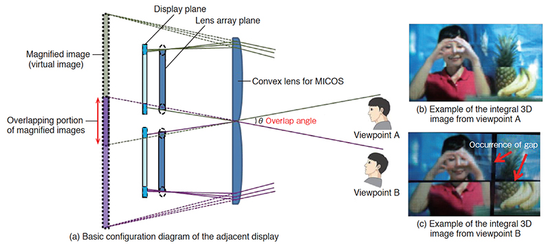
Figure 4(a) illustrates the case in which the centers of the convex lens and the lens array plane lie on the same vertical axis—that is, no eccentricity is applied to the convex lenses. Denoting the distance between the lens array plane and the convex lens by a, the distance between the virtual-image plane and the convex lens by b, the width of the display's image-display region (the width of the lens array plane) by w1, and the width of the overall display including bezels (the width of the convex lens) by w2, the length l and overlap angle θ of the overlap region are given by


From Equations (1) and (4), we can see that the overlap angle θ may be increased by increasing the distance a between the lens array plane and the convex lens; however, this has the problem of increasing the size of the overall system in the depth direction. To expand the overlap angle without increasing the system dimensions, we introduce an outward shift (eccentricity) of the center of the convex lenses, as shown in Fig. 4(b). Because the virtual images accordingly shift inward, the overlap region of the enlarged images expands, broadening the overlap angle. Denoting the eccentricity by d and the convex-lens focal length by fc, the length l' and overlap angle θ' of the overlap region of the magnified images are given by


4. Experimental results
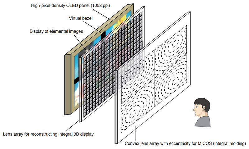
We used high-pixel-density displays, lens array, and a MICOS to conduct screen-synthesis experiments of integral 3D images. Figure 5 shows a configuration of our prototype system, and its specifications are detailed in Table 1. The displays we used were high-pixel-density OLED panels14) with 8K resolution and 1,058 ppi (pixels per inch) from Semiconductor Energy Laboratory Co., Ltd. We input a black image (virtual bezel) into a portion of the display region, virtually divide this region into four subregions, and use our MICOS to stitch together these four subimages. The elemental images for input to the four display areas were created by considering the overlapping portion of the magnified image. Also, to minimize unnatural aspects of the image-stitching regions in the MICOSs, multiple convex lenses for combining multiple images were integrally molded on a single acrylic plate to form a Fresnel lens*8 array and thus reduce the unnaturalness of the image connecting portion.
| Number of pixels per single display | 3,673×2,066 |
|---|---|
| Number of display areas | 4 |
| Pixel density of display panel (ppi) | 1,058 |
| Pitch of lens array (mm) / focal length of lens array (mm) | 0.5 / 1.06 |
| Focal length of convex lens for MICOS (mm) | 175 |
| Number of elemental images after screen synthesis | 311×175 |
| Viewing angle (degrees) | 20.6 (both horizontal and vertical) |
| Size of individual screens before screen synthesis (inches) | 4.0 diagonal |
| Size of four-screen-synthesized image (inches) | 9.1 diagonal |
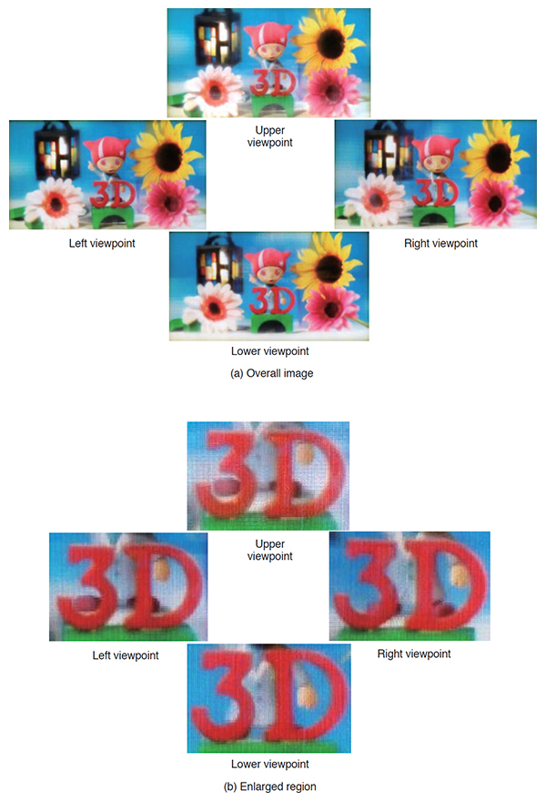
The diagonal size of each screen (each individual region) is 4.0 inches, and synthesizing the four screens yields a 311×175 array of elemental images (3D image pixel count), creating an integral 3D image with a screen size of 9.1 inches and viewing angles of 20.6 degrees in both horizontal and vertical directions. Figure 6 shows integral 3D images obtained by synthesizing four screens. Figure 6(a) shows the variation in reproduced 3D images when seen from different viewpoints. As is evident from the enlarged images in Fig. 6 (b), it can be seen that there is motion parallax in the positional relationship between the character "3D" and the hand of the doll, according to the viewpoints.
The full size of the entire prototype system in the depth direction is 47 mm, a dramatic reduction in thickness compared with the 600 mm sizes typical of conventional screen-synthesis systems12) 13). Also, we measured and compared MTF (modulation transfer function) *9 values at various spatial frequencies for our prototype system and a conventional prototype system (which synthesizes images from four direct-view displays using parallel light, a MICOS, and a diffuser plate); the comparison revealed that our system produces significantly improved MTF values at all spatial frequencies, confirming the high quality of the screen synthesis and outstanding resolution characteristics of our proposed technique (Fig. 7).

5. Conclusions
In this work, we proposed a method of increasing pixel counts by using multiple direct-view displays to synthesize integral 3D images. In contrast to conventional MICOS12) 13), the MICOS we propose is simple and requires no diffuser plates. In addition to enabling high-quality screen synthesis with outstanding resolution properties, our approach also enables a reduction in the depth of the overall device.
We also proposed a technique for expanding effective viewing angles for integral 3D images by applying eccentricity to the MICOS. Finally, we constructed a prototype system involving high-pixel-density OLED panels with 8K resolution and demonstrated integral 3D imaging with an increased pixel count via screen synthesis.
The method proposed in this paper, which enables increased pixel counts with high-quality images using a compact system assembly, has potential for applications in broadcasting, industry, and other fields as an elemental technology for future 3D display.
Acknowledgements
Portions of this work were carried out in collaboration with Semiconductor Energy Laboratory Co., Ltd., and high-pixel-density OLED panels from Semiconductor Energy Laboratory Co., Ltd., were used.
This manuscript is a revised and extended version of the following article, published in the Journal of the Society for Information Display:
N. Okaichi, M. Kawakita, H. Sasaki, H. Watanabe, T. Mishina: "High-quality Direct-view Display Combining Multiple Integral 3D Images," J. Soc. Inf. Display, Vol.27, No.1, pp.41-52 (2018)