Super Hi-Vision Terrestrial Transmission Test
Makoto Taguchi
NHK STRL is researching large-capacity terrestrial transmission technology for large-volume content services such as Super Hi-Vision. We have studied a new transmission system that is based on the conventional ISDB-T digital terrestrial television broadcasting system. The new system uses dual-polarized MIMO and ultra-multilevel OFDM. This paper describes field experiments conducted in the urban area around the STRL building using a prototype modulator and demodulator and LDPC and BCH coding for forward error correction (FEC). It also describes a terrestrial field experiment on encoded and compressed Super Hi-Vision signals in which the transmission capacity was greatly increased by applying a bulk transmission scheme using two UHF channels.
1. Introduction
STRL has been doing R&D on Super Hi-Vision television broadcasting, which can create the feeling of immersion and sense of presence for viewers. Super Hi-Vision is an audio-video system that comprises ultra-high-definition video images with 16 times as many pixels as Hi-Vision and 22.2 multi-channel three-dimensional sound. Highly efficient large-capacity transmission technology is essential for delivering Super Hi-Vision and other such high-volume content services over terrestrial broadcasting.
We have investigated a system based on the current ISDB-T terrestrial digital transmission system that increases the number of carrier modulation levels and uses polarized MIMO technology (both horizontal and vertical polarizations simultaneously) to greatly increase transmission capacity1)2)3)4)5)6)7). We have also conducted field tests on a prototype system in which the capacity was increased by combining this technology with simultaneous bulk transmission over two UHF channels. The results showed that terrestrial transmission of compressed and encoded Super Hi-Vision signals was possible.
Here, we present the results of these field tests of polarized MIMO-ultra-multilevel OFDM transmission and terrestrial transmission of Super Hi-Vision.
2. Field transmission tests
To clarify the transmission characteristics of polarized MIMO-ultra-multilevel OFDM in an urban environment, we did field tests using pseudo-random noise (PN) signals.
2.1 Specifications of the transmitting and receiving equipment
The specifications of the transmitting and receiving equipment are listed in Table 1. The transmission frequency was 599.142857 MHz (channel 34) and the transmission output was 1 W each for the horizontal and vertical polarizations.
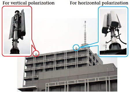
We used two antennas that are installed on the roof of the STRL building to separately transmit horizontal and vertical polarization signals. Although the transmitting antennas are on the same building (Figure 1), they are separated by some distance. 4L dual-loop antennas (1 stage, 2 planes) were used for both polarizations. The antenna height above the ground was 74 m.
The receiving antenna was a dual-polarization eight-element Yagi antenna (Figure 2) that can receive horizontal and vertical polarizations simultaneously. The gain of the receiving antenna was 9.2 dBd*1 for the horizontal polarization and 10.3 dBd for the vertical polarization; the cross polarization discrimination*2 was 20 dB or more in the forward direction. The receiving antenna height above the ground was 10 m.
| Transmission frequency (MHz) | 599.142857 (34ch) |
|---|---|
| Transmission output (W) | Horizontal polarization : 1 Vertical polarization: 1 |
| Transmitting antenna | 4L dual-loop antenna, 1 stage, 2 planes |
| Transmitting antenna height above ground (m) |
74 |
| Receiving antenna | Dual-polarization 8-element Yagi antenna |
| Receiving antenna height above ground (m) |
10 |
(4L dual-loop antenna (1 stage, 2 planes))

(dual-polarization 8-element Yagi antenna)
2.2 Transmission parameters
The transmission parameters used in the test are listed in Table 2. The transmission frequency bandwidth was 5.57 MHz. Three carrier modulation schemes were used: 256 QAM, 1024 QAM, and 4096 QAM. The FFT size was 8 k (8,192) points, the number of carriers was 5,617, the guard interval was 126 µs, and the guard interval ratio was 1/8. The inner code was irregular LDPC*3 with a code length of 64,800 bits and encoding ratio of 3/4. The outer code was BCH. The maximum transmission capacity for the 4096 QAM carrier modulation scheme was 39.5 Mbps for a single polarization and 78.9 Mbps for both polarizations. The horizontal and vertical polarizations were modulated with different PN signals.
| Transmission parameters | ||
|---|---|---|
| Frequency bandwidth (MHz) | 5.57 | |
| Carrier modulation scheme | 256QAM, 1024QAM, 4096QAM | |
| FFT size | 8k (carriers: 5,617) | |
| Guard interval (µs) | 126 | |
| Guard interval ratio | 1/8 | |
| FEC*(error correction) | Inner code | Irregular LDPC code (code length: 64,800, code rate: 3/4) |
| Outer code | BCH code | |
| Transmission capacity (Mbps) |
39.5 (4096 QAM, single polarization used) 78.9 (4096 QAM, both polarizations used) |
|
| Number of measurement points |
23 | |
*Forward Error Correction
2.3 Measurement locations
We selected 23 sites around STRL at which the electric field strength for the horizontal polarization would be at least 50 dBµV/m (Figure 3). The transmission point was the STRL building (center of Figure 3). The blue line in the figure indicates where the estimated horizontal polarization electric field strength is 50 dBµV/m; the red line marks the estimated electric field strength of 60 dBµV/m. The blue circles indicate the measurement points. All of the measurement points were in an urban area and were 0.9 km to 4.6 km from the transmission point.

2.4 Test system
The two modulated signals output from the modulator for the horizontal and vertical polarizations were transmitted from two antennas and received by a single dual-polarization Yagi antenna. The receiving system is shown in Figure 4. The two received signals output from the receiving antenna were passed through respective band-pass filters, attenuated by a variable attenuator, amplified by a low-noise amplifier, and then converted to IF signals by a down-converter. The two IF signals were input to a polarized MIMO-ultra-multilevel OFDM demodulator for demodulation and decoding, and the bit error rate (BER) of the bit stream for each polarization output from the demodulator was measured. At each measurement location, the received electric field strength, the BER after LDPC decoding, the required electric field strength (minimum received electric field strength for a BER of 1 x 10⁻⁷ after LDPC decoding and a quasi-error-free (QEF) signal after BCH decoding) were measured and a line-of-sight transmission path was confirmed.

2.5 Test results
The received electric field strength measurements for the 23 locations are presented in Figure 5, where the horizontal axis indicates the measurement site and the vertical axis indicates the received electric field strength. We can see from the figure that the received electric field strength ranged from 40 dBµV/m to 80 dBµV/m and the maximum difference in received electric field strength between the polarizations was 6.5 dB. There was a line-of-sight (LOS) transmission path for 14 sites and a non-line-of-sight (NLOS) path for the other 9 sites. Also, measurement location 9 was in the shadow of a building, so the received electric field strength was very small there.
Figure 6 shows the relation between the average received electric field strength for the two polarizations and the transmission distance. Twelve of the LOS path measurement sites (indicated by solid blue circles in the figure) received QEF transmissions for both polarizations up to 4096 QAM. Two sites (solid orange triangles) received QEF transmissions for both polarizations up to 1024 QAM. Even for the NLOS paths, three sites received QEF transmissions up to 4096 QAM (open blue circles) and two sites received them up to 1024 QAM (open orange triangles). Moreover, two NLOS locations (open green squares) received QEF transmissions with 256 QAM but two others (the purple x's) did not. The solid lines in Figure 6 indicate the received electric field strength calculated under the assumption that all of the propagation loss was free-space. The average received electric field strength is fairly close to the calculated electric field strength for the 14 LOS measurement sites, but it is lower than the calculated value by at least 10 dB for the nine NLOS sites.
Table 3 lists the number of measurement sites at which QEF transmission is possible for both polarizations for each carrier modulation scheme. These results confirm that QEF transmission is possible with 4096 QAM when the received electric field strength is high, even to NLOS locations.
We obtained the required electric field strength for each carrier modulation scheme by measuring the BER after LDPC decoding for each polarization for various degrees of attenuation of the receiving antenna output for each polarization at each of the measurement sites (Table 4). For 256 QAM, the required electric field strength is averaged over 22 sites for horizontal polarization and over 21 sites for the vertical polarization; for 1024 QAM, the average is over 20 sites for both polarizations; for 4096 QAM, the average is over 19 sites for horizontal polarization and 16 sites for vertical polarization. Table 4 shows that the average required electric field strength was 46.2 dBµV/m for 256 QAM carrier modulation, 51.3 dBμµV/m for 1024 QAM, and 56.7 dBµV/m for 4096 QAM.
The above data confirm the possibility of QEF transmission of polarized MIMO-ultra-multilevel OFDM signals even in an urban propagation environment with some degree of multipath propagation.


| Carrier modulation scheme | LOS environment (14 sites) |
NLOS environment (9 sites) |
|---|---|---|
| 4096QAM | 12 | 3 |
| 1024QAM | 14 | 5 |
| 256QAM | 14 | 7 |
| Carrier modulation scheme | Average required electric field strength (dBµV/m) |
|---|---|
| 256QAM | 46.2 |
| 1024QAM | 51.3 |
| 4096QAM | 56.7 |
3. Super Hi-Vision terrestrial transmission tests
The capacity of a single UHF channel with polarized MIMO-ultra-multilevel OFDM transmission is 78.9 Mbps, which is insufficient for Super Hi-Vision signals. We therefore combined polarized MIMO-ultra-multilevel OFDM technology with bulk transmission technology that uses two UHF channels simultaneously to at least double the transmission capacity (183.6 Mbps) in a prototype transmission system. We increased the FFT size to 32 k (32,768) points and optimized the transmission parameters. The prototype transmission equipment used polarization interleaving to reduce the degradation of the transmission characteristics caused by differences in the received signal characteristics of the two polarizations. We also developed a TS signal splitter for separating one SHV-TS (Transport Stream) into two TS signals for bulk transmission and a combiner for combining the two received TS signals and restoring the original signal. The prototype transmission equipment was used in terrestrial transmission field tests of a compressed and encoded Super Hi-Vision signal (182 Mbps).
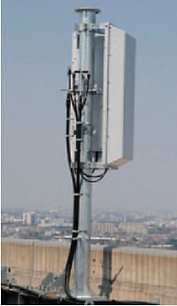
3.1 Dual-polarization transmitting antennas
We constructed a prototype dual-polarization transmitting antenna that can transmit vertically and horizontally polarized signals simultaneously from a single antenna and installed it on the roof of the STRL building. The dual-polarization transmitting antenna used in the tests is shown in Figure 7. Inside the lightning protection cover, dipole elements for the horizontal and vertical polarizations are arranged in multiple stages to attain the same gain and directionality as the dual-loop antenna (four-loop) used at relay stations in current terrestrial digital transmission. A cross polarization discrimination of 25 dB or more was obtained within a range of about 150° in the horizontal plane.
3.2 TS splitter and combiner
For bulk transmission of a single SHV-TS signal over two channels, the SHV signal has to be split into two TS signals and the received signals have to be recombined in order to restore the original signal. We developed a TS splitter and TS combiner for this purpose.
3.3 Test system
Figure 8 shows the system for testing terrestrial Super Hi-Vision transmissions . The upper part of the figure is the transmission side of the system; the lower part is the receiving side. On the transmission side, a compressed and encoded SHV-TS signal was played by an SHV-TS player and output to a TS splitter. The TS splitter divided the SHV signal into two TS signals, which were then input to their respective polarized MIMO-ultra-multilevel OFDM modulators to produce IF signals. Next, the four modulated signals were converted to UHF channel 31 and channel 34 radio frequency (RF) signals and amplified to the specified output of 1 W. The two RF signals were then combined by the respective antenna duplexers into horizontal and vertical polarization signals and transmitted from the dual-polarization transmitting antenna installed on the roof of the STRL building.
One the receiving side, a single dual-polarization Yagi antenna received signals of both polarizations. The two received signals (RF signals) were amplified with a booster amplifier and split into the respective channels. Each polarization of each channel was input to a receiver and converted to an IF signal, resulting in a total of four IF signals. The two IF signals of each channel were demodulated and decoded by polarized MIMO-ultra-multilevel OFDM demodulators and converted into a TS signal. The TS combiner combined the two TS signals output from the demodulators into a single SHV- TS signal, which was then converted into an SHV video signal by the SHV decoder.

3.4 Test specifications
The specifications for the SHV terrestrial transmission tests are listed in Table 5. The Super Hi-Vision video signal was compressed and encoded with the MPEG-4 AVC/H.264 codec to 182 Mbps to create a data stream that would be within the transmission equipment capacity of the test system (183.6 Mbps with two channels). The signal was transmitted from a prototype multi-stage dipole dual-polarization transmitting antenna installed on the roof of the STRL building. The transmission height of the antenna was 74 m above the ground.
A dual-polarization eight-element Yagi antenna was installed on the roof of a building at the receiving site, 4.2 km north by northwest from the transmitting antenna. The signal propagation environment was an urban area with a quasi-line-of-sight path due to the presence of trees.
| Carrier modulation scheme | 4096QAM | |
|---|---|---|
| FFT size | 32k (Number of carriers: 22,465) | |
| Guard interval (µs) | 126 | |
| Guard interval ratio | 1/32 | |
| Error correction | LDPC (code rate: 3/4)+ BCH) | |
| Interleaving | Bits, Frequency, Time, Between polarizations | |
| Two-channel transmission capacity (Mbps) |
183.6 | |
| Transmission output(W) | 31ch (H): 1 34ch (H): 1 |
31ch (V):1 34ch (V):1 |
| Transmission frequency (MHz) | 581.142857 (UHF 31ch) 599.142857 (UHF 34ch) |
|
| Video encoding | MPEG-4 AVC/H.264 | |
| TS rate after compression and encoding (Mbps) |
182 | |
3.5 Test results
The electric field strength and the received signal modulation error ratio (MER)*4 were measured at the reception site (Table 6). The electric field strength was about 60 dBµV/m for all channels and all polarizations. The MER, however, was particularly low for the vertical polarization in channel 34. The low MER was considered to be an effect of same-channel interference from a terrestrial digital transmission signal arriving at the receiving site from nearly the same direction as the test transmission. The results confirm that a stable, error-free SHV video signal can be output by the SHV decoder even in the presence of co-channel interference in the propagation environment.
| Channel | 31ch | 34ch | ||
|---|---|---|---|---|
| Polarization | Horizontal | Vertical | Horizontal | Vertical |
| Electric field strength (dBµV/m) |
62.1 | 58.9 | 60.0 | 58.0 |
| MER (dB) | 42.1 | 39.5 | 38.7 | 35.7 |
4. Conclusion
We are researching and developing technology for large-capacity transmission of next-generation terrestrial television (Super Hi-Vision) services. We tested a system for terrestrial transmission that combines our previously developed polarized MIMO-ultra-multilevel OFDM transmission technology with bulk transmission over two UHF channels. The tests used a larger FFT size of 32k points together with LDPC and BCH coding. We implemented polarization interleaving to reduce degradation in transmission characteristics caused by differences in the reception characteristics between polarizations. We also constructed a prototype TS splitter for dividing an SHV-TS signal into two streams for transmission and a combiner for restoring the single signal on the receiving side. The test results confirmed that a stable, error-free SHV video signal could be received at a distance of 4.2 km from the transmission site in an urban quasi-line-of-sight propagation environment. In the future, we plan to increase the number of measurement sites and do a detailed analysis of the characteristics of various transmission paths.
This article adds to and revises the following papers from the IEEE International Symposium on Broadband Multimedia Systems and Broadcasting (BMSB 2012) and published in the ITE Technical Reports.
T. Shitomi, K. Murayama, M. Taguchi, S. Asakura, and K. Shibuya: "Technology for Next-generation Digital Terrestrial Broadcasting: Field Experiments of Dual-polarized MIMO-OFDM Transmission using LDPC Codes," IEEE International Symposium on Broadband Multimedia Systems and Broadcasting (BMSB 2012), mm12-016 (2012)
Murayama, Taguchi, Shitomi, Asakura, and Shibuya: "Transmission Technology for Next-generation Terrestrial Broadcasting: Testing of SHV Transmission using Two UHF Channels," ITE Tech. Reports, Vol. 36, No. 30, BCT2012-64, pp. 17-20 (2012)