Research Area
1.1 3D imaging technology
With the goal of developing a new form of broadcasting, NHK STRL is researching a spatial imaging three-dimensional (3D) television that shows more natural 3D images to viewers without special glasses. We conducted research on capture, display and coding technologies for high-resolution 3D images and on a 3D imaging technology for portable terminals for personal viewing. For the practical use of these technologies, we also worked to identify the characteristics of 3D images and the requirements for 3D imaging systems that are suitable for diverse viewing environments.
■High-resolution 3D imaging technology
To capture high-resolution 3D images, we developed a technology for generating 3D images from images captured with a camera array(1). This technology performs viewpoint interpolation process on the 154-viewpoint images captured with a camera array consisting of 154 HD cameras (Figure 1-1 (a)) to generate images of as many viewpoints as needed for 3D displays (Figure 1-1 (b)). This viewpoint interpolation process estimates the depth of an object from multi-view images and determines the pixels of interpolated images from the color information of the pixels of camera images. This technology enabled the generation of 3D images that have about 330,000 pixels. Using a prototype system, we captured persons and clay animations and exhibited the generated 3D images at the NHK STRL Open House 2018.
As a technology for displaying high-resolution 3D images, we developed a system called Aktina Vision, which uses multiple projectors and a special diffusion screen(2). This system reproduces high-density multi-view images by arranging multiple projectors and superimposes the images on the display screen through an optical system. This enables the display of high-resolution 3D images (Figure 1-2 (a)). It can display 3D images with reduced crosstalk of light between light rays by adapting the diffusion characteristics of the display screen to the angle between projected light rays. Since the resolution of displayed 3D images agrees with the resolution of images from each viewpoint in this system, the resolution of 3D images can be increased more easily than the lens array system by increasing the resolution of multi-view images. Our prototype of this system using fourteen 4K projectors achieved the display of 3D images having 330,000 pixels, about three times that of a prototype lens-array system that we fabricated in FY 2017 (Figure 1-2 (b)).
Since high-resolution 3D images contain a huge amount of information, it is necessary to develop a high-efficiency coding technology to realize a 3D television. We continued to attend MPEG meetings and promoted standardization activities for 3D video coding standards. We conducted experiments on applying existing coding schemes to the test sequences of elemental images provided to the MPEG meeting and submitted the results to the meeting as input to contribute to the promotion of standardization.
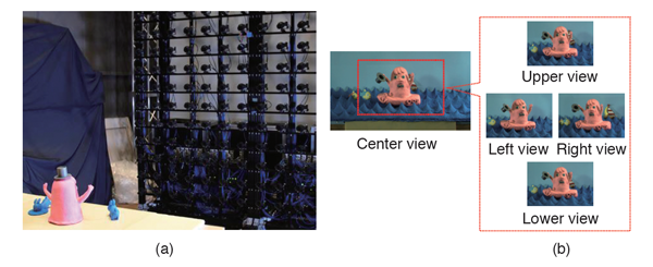
Figure 1-1. High-resolution 3D capture technology (a) Capture using a camera array (b) Examples of images generated from camera images by viewpoint interpolation
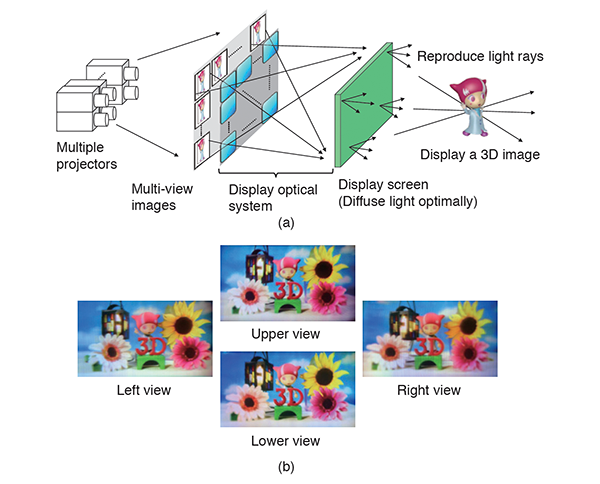
Figure 1-2. Aktina Vision (a) Configuration diagram (b) Displayed images from various viewpoints
■3D imaging technology for portable terminals
We continued with our R&D on integral 3D display with eye-tracking system with the aim of realizing a 3D image viewing service using portable devices for personal viewing. In FY 2018, we developed a method for the real-time generation of 8K elemental images in accordance with the viewer's eye position and a viewing-zone formation method suitable for eye-tracking display(3). Our prototype equipment using a high-pixel-density 8K organic light-emitting diode (OLED) display with a pixel density of 1058 ppi (pixel per inch) produced by Semiconductor Energy Laboratory Co., Ltd. achieved about 3.3 times the horizontal viewing zone and about 6.6 times the vertical viewing zone of a conventional device (Figure 1-3). The use of a lens array with a long focal length also almost doubled the light density for reproducing 3D images in both the horizontal and vertical directions over a prototype that we fabricated in FY 2017. This led to the improvement in image quality.
The integral method displays 3D images by adhering a lens array to elemental images shown on a direct-view display. This method, however, causes color moiré because the display's subpixel structure of red (R), green (G) and blue (B) is observed through a lens array. To reduce the color moiré, in FY 2018, we developed a method for optically shifting the pixels of elemental images in a time-sharing manner and multiplexing them. We conducted experiments to verify the operating principle of a system combining an OLED display (produced by Semiconductor Energy Laboratory Co., Ltd.), a lens array, and an optical wobbling device consisting of a double refraction element and a polarization control element (Figure 1-4). The results demonstrated that the system can reduce the color moiré to 66% that of a conventional device.
As a wide-viewing-zone imaging method suitable for 3D images on portable terminals, we studied a method for generating 3D models of an object from multi-view images and converting them into elemental images. In FY 2018, we produced high-quality 3D image content using a 3D model generation technology that supports 4K multi-view robotic cameras and a nonlinear depth compression technology. We also prototyped a stereo robotic cameras system to generate integral 3D images having a wider viewing zone with a smaller number of cameras (Figure 1-5). This system can control the directions of its three robotic cameras simultaneously, enabling camera work such as panning, tilting and zooming while capturing multi-view images of a 3D image reproduction area in a real space.
We investigated applications using the 3D imaging technology for portable terminals. As examples of such applications, we prototyped integral 3D displays (a table-shaped one and a smartphone-shaped one) that show 3D images in the air by using an optical system. We also prototyped an application that delivers and displays 3D images linked with 2D TV images on a 3D display and a system that enables 3D image viewing with an interactive operation. We exhibited them at the NHK STRL Open House 2018 (Figure 1-6).
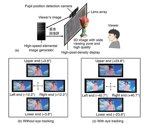
Figure 1-3. Integral 3D display with eye-tracking system (a) System configuration and viewing angle (b) Without eye tracking (c) With eye tracking
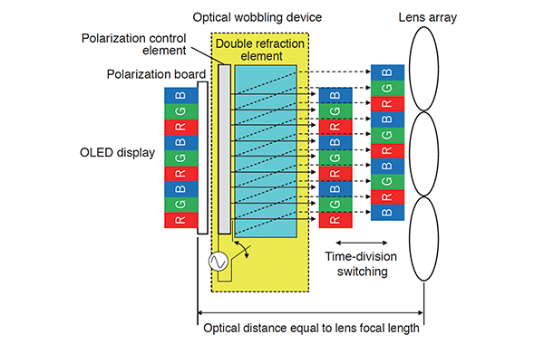
Figure 1-4. Structure of color moiré reduction method using optical wobbling device
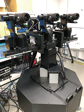
Figure 1-5. Stereo robotic cameras system

Figure 1-6. Interaction between 2D TV and table-type 3D display
■3D image characteristics and 3D imaging system requirements suitable for the viewing environment
We are engaged in research to identify 3D image characteristics and 3D imaging system requirements that are suitable for diverse viewing environments. In FY 2018, we developed a new depth-compression method that could increase the quality of integral 3D display, which is a 3D imaging technology, and evaluated the influence of depth compression in a portable 3D display environment through psychological experiments.
In the integral method, an image tends to appear blurry when it is reproduced at a distance in the depth direction from the lens array on the display surface. To reduce the blurring, we use depth-compression expression that compresses the entire reproduced scene into a narrow depth while appropriately deforming the shape of the object to ensure the naturalness of its appearance. In the conventional (unidirectional) depth-compression technology, the shape of an object was compressed in the depth direction (the normal direction to the display surface). This caused a larger sense of unnaturalness when the viewer viewed the reproduced image obliquely from a different position from the original viewpoint because the deformation of the object was recognized. We therefore investigated an omnidirectional depth-compression method that compresses the object shape and space centering on the viewpoint. This method expresses a scene in a space of 3D polar coordinates whose origin point is the viewpoint and compresses the objects in the scene in the radial direction. This is expected to reduce the degree of recognizable deformation because the angular difference between the line of sight and the compression direction becomes smaller than that of the conventional method.
We analyzed and quantitatively evaluated the extent to which objects are deformed for display (the amount of distortion) when applying the unidirectional and omnidirectional depth-compression methods (Figure 1-7). We defined the amount of distortion on the basis of the ratio of the distance between two points on a 2D image that the viewer sees between before and after depth compression and used a scale with 0 for no deformation and a larger value for larger deformation. The results showed that the proposed method was more effective for reducing the amount of distortion and producing more natural expression than the conventional method particularly when the viewpoint position moved greatly in the horizontal direction (far-right upper and lower charts in Figure 1-7)(4).
Assuming a 3D image viewing environment using portable terminals, we conducted subjective evaluations in terms of the naturalness of depth-compressed images. For the experiments, it is necessary to evaluate the distortion of space and shape regardless of the depth reconstruction characteristics of the display equipment, but currently available integral 3D displays cannot provide a sufficient depth reconstruction range. We therefore developed a new experimental equipment for evaluation (Figure 1-8).
This equipment, which consists of a active shutter 3D system and a device for measuring the viewpoint position, displays images drawn in accordance with the viewpoint position and the display attitude. This enables the presentation of 3D images having motion parallax, which is a feature of the integral method. It is also possible to handle, with a small force, the position and direction of the display, which is suspended from the ceiling by a constant force spring and a wire.
The participants evaluated the unnaturalness of depth-compressed images (scenes with original depth ranges of 0.2 - 50 m compressed into 0.1 - 5 m). Figure 1-9 shows the relationship between the depth range after compression and the evaluation scores of naturalness. The results demonstrated that the minimum depth range for causing unnaturalness equal to or higher than the acceptable threshold (MOS = 3.5) was about 1.3 m. This value slightly exceeds the result (1 m) previously obtained in a viewing environment with a fixed display (standard TV in living room). The unnaturalness after depth compression tends to be conspicuous when the viewpoint moves largely. This is considered to be the reason why the range after necessary depth compression slightly increased for a viewing environment using portable terminals, on which relative viewpoint movement tends to be larger.
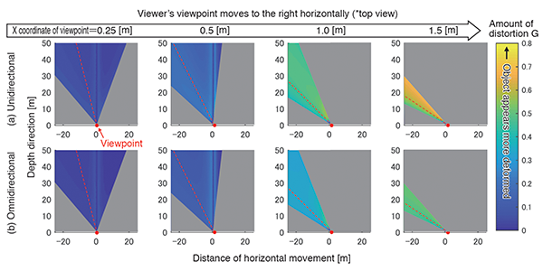
Figure 1-7. Comparison of the distortion amount at viewpoint movement between unidirectional and omnidirectional depth compressions
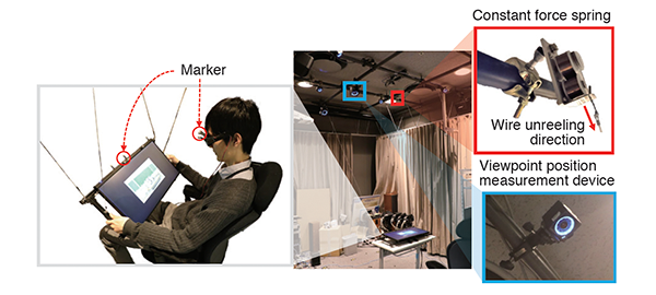
Figure 1-8. Experimental equipment for 3D imaging evaluation simulating a viewing environment with portable terminals
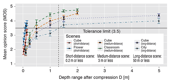
Figure 1-9. Relationship between the depth range after compression and the evaluation scores of naturalness
| [References] | |
| (1) | M. Kano, H. Watanabe, M. Kawakita and T. Mishina: "3D Imaging with 330,000 Pixels Using Camera Array," ITE Winter Annual Convention 2018, 23D-1 (2018) (in Japanese) |
| (2) | H. Watanabe, N. Okaichi, T. Oomura, M. Kano, H. Sasaki and M. Kawakita: "Light field display system with resolution of 330,000 pixels using top-hat diffusing screen," ITE Winter Annual Convention 2018, 23D-2 (2018) (in Japanese) |
| (3) | N. Okaichi, H. Sasaki, H. Watanabe, K. Hisatomi and M. Kawakita: "Integral 3D display with eye-tracking system using 8K display," ITE Winter Annual Convention 2018, 23D-3 (2018) (in Japanese) |
| (4) | Y. Miyashita, Y. Sawahata, T. Morita, K. Komine: "Design of depth compression method for natural 3D visualization," ITE Annual Convention 2018, 12A-1 (2018) (in Japanese) |